

 See My Latest Article on HelloNation
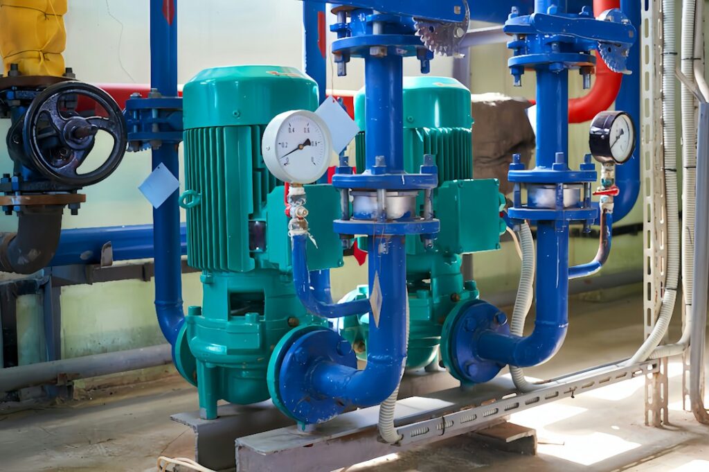
Industrial pumps are mechanical devices that move liquids, slurries, and, in some cases, liquid-gas mixtures through a controlled system. They create the pressure or flow needed to transfer fluid between tanks, raise it to a higher elevation, circulate it through equipment, or deliver it at a steady rate for processing.
For residents and facility operators in Quincy, IL, pumps may be part of water treatment, wastewater collection, food processing, agricultural operations, heating and cooling systems, or manufacturing processes. Although pumps can appear simple from the outside, their performance depends on the interaction of the pump, motor, piping, valves, controls, and the fluid being moved.
What does a pump actually do?
A pump adds energy to a fluid. That energy allows the fluid to overcome elevation changes, friction in piping, pressure differences, and resistance from equipment such as filters, heat exchangers, spray systems, or process vessels.
A pump does not create liquid. It moves an available supply from one location to another. A complete pumping system normally includes:
- A pump
- An electric motor or other driver
- Suction and discharge piping
- Valves and strainers
- Tanks, basins, or process equipment
- Pressure, temperature, flow, or level instruments
- Controls and protective devices
The pump’s job is only one part of the overall system. A correctly selected pump can still perform poorly if the piping is undersized, a valve is improperly positioned, or the liquid contains more solids or air than expected.
How does a centrifugal pump work?
Centrifugal pumps use a rotating impeller to increase the velocity of a liquid. The liquid enters near the center of the impeller, moves outward as the impeller spins, and then passes through the pump casing. The casing slows the liquid and converts much of its velocity into pressure.
This type is widely used because it can provide continuous flow with relatively few moving parts. Common applications include:
- Cooling-water circulation
- Boiler and heating-water systems
- Process-water transfer
- Irrigation and drainage
- Wastewater movement
- Chemical and food-processing liquid transfer
Centrifugal pumps generally work best with relatively steady flow and liquids that are not excessively thick. Their flow changes as system resistance changes. If downstream pressure or friction increases, the pump usually delivers less flow.
A common misconception is that a larger pump always performs better. An oversized pump may create excessive pressure, waste energy, cause control valves to operate nearly closed, and increase wear on piping and equipment. Proper sizing depends on the required flow, total pressure, fluid properties, operating schedule, and future system conditions.
What is a positive-displacement pump?
Positive-displacement pumps move a measured volume of fluid during each cycle or shaft rotation. The pump traps liquid in a chamber and then forces it into the discharge piping. Examples include piston, diaphragm, gear, screw, and progressive-cavity pumps.
These pumps are useful when the process requires:
- High pressure at a controlled flow
- Accurate dosing or metering
- Movement of thick liquids
- Handling of slurries or fluids with suspended material
- Flow that must remain relatively consistent as pressure changes
Unlike a typical centrifugal pump, a positive-displacement pump can continue building pressure if its discharge path is blocked. For that reason, these systems require pressure relief protection and carefully selected controls. Operating a positive-displacement pump against a closed valve can damage equipment or create a serious safety hazard.
What is pump head, and why is it different from pressure?
Pump “head” is a way of describing the energy added to a fluid, usually expressed as a height of liquid. Pressure is measured in units such as pounds per square inch, while head describes how high a pump could theoretically raise a fluid under defined conditions.
A pump must overcome several forms of resistance:
- Static elevation, such as lifting water to a higher tank
- Friction from pipe walls, fittings, elbows, and valves
- Equipment resistance from filters, heat exchangers, and nozzles
- Pressure already present in the receiving vessel
- Changes in fluid density and viscosity
The required pump head is not simply the building height. A long pipe run can produce substantial friction loss even when the elevation change is modest. Conversely, a short system may require significant pressure if it feeds a pressurized vessel or specialized process equipment.
Why is suction piping so important?
The suction side supplies liquid to the pump inlet. Poor suction conditions can cause cavitation, air binding, vibration, loss of capacity, and premature damage.
Cavitation occurs when local liquid pressure falls low enough for vapor bubbles to form. Those bubbles collapse as the liquid reaches higher pressure inside the pump, creating noise, vibration, and erosion of the impeller or other internal surfaces.
Good suction design generally includes:
- Adequate pipe diameter
- Short, direct piping where practical
- Properly supported pipe that does not strain the pump casing
- Fully open and correctly sized suction valves
- A reliable liquid supply above or near the pump inlet
- Protection against air leaks and vortex formation

Air can be especially troublesome because a pump designed for liquid may not be able to move air effectively. A system may appear to have a pump failure when the actual problem is an empty suction line, a leaking gasket, or an improperly located intake.
How do controls regulate pump operation?
Pump controls coordinate flow, pressure, level, temperature, and equipment protection. A simple system may start a pump when a tank level rises and stop it when the level falls. More advanced systems use sensors and variable-speed drives to adjust motor speed as demand changes.
Variable-speed operation can reduce energy use in systems that do not need full flow all the time. It can also reduce water hammer, pressure swings, and mechanical stress during starting and stopping. However, changing speed changes pump performance, and the motor, pump, controls, and piping must be evaluated as one system.
In wastewater applications, level controls may start pumps in a wet well and provide alarms for high levels, power loss, or equipment faults. In industrial settings, interlocks may prevent a pump from running without adequate liquid, cooling, lubrication, or open flow paths.
What pump problems are most common?
Many pump problems begin outside the pump itself. Symptoms and likely causes often include:
- Low flow: clogged strainers, closed valves, worn impellers, incorrect rotation, or excessive system resistance
- Excessive vibration: cavitation, misalignment, imbalance, poor pipe support, or bearing damage
- Noise: air in the suction line, cavitation, loose components, or a damaged coupling
- Overheating: inadequate lubrication, excessive load, blocked cooling, or operation far from the intended design point
- Repeated seal leakage: shaft movement, misalignment, abrasive fluid, dry running, or incorrect seal materials
- Frequent cycling: poor tank sizing, faulty level controls, or a pump that is too large for the demand
Seasonal conditions can also affect local systems. Freezing temperatures can damage exposed piping, seals, gauges, and valves. Heavy rainfall may increase flows entering drainage or wastewater systems, while suspended solids can increase wear in pumps handling stormwater or process waste.
Why does maintenance involve more than changing oil?
Pump maintenance includes observing operating conditions, checking for leaks, inspecting seals and bearings, verifying alignment, cleaning strainers, testing alarms, and comparing actual flow and pressure with expected values.
Useful records may include:
- Motor amperage
- Suction and discharge pressure
- Flow rate
- Vibration or noise changes
- Seal leakage
- Start-and-stop frequency
- Temperature readings
- Alarm history
A gradual change is often more informative than a single reading. A pump that remains operational but requires increasing power to deliver the same flow may be experiencing blockage, wear, changing fluid conditions, or a system restriction.
Industrial pumps function reliably when the entire system is designed and operated as a connected process. Understanding the pump type, fluid properties, system resistance, suction conditions, controls, and maintenance history makes it easier to identify problems before they interrupt production, water service, treatment operations, or other essential activities.